Spinning a Laser Printer Polygon Mirror
I want to play around with laser direct imaging, so I bought an old laser printer for it’s spinning polygon mirror. This blog post is how I got it spinning.
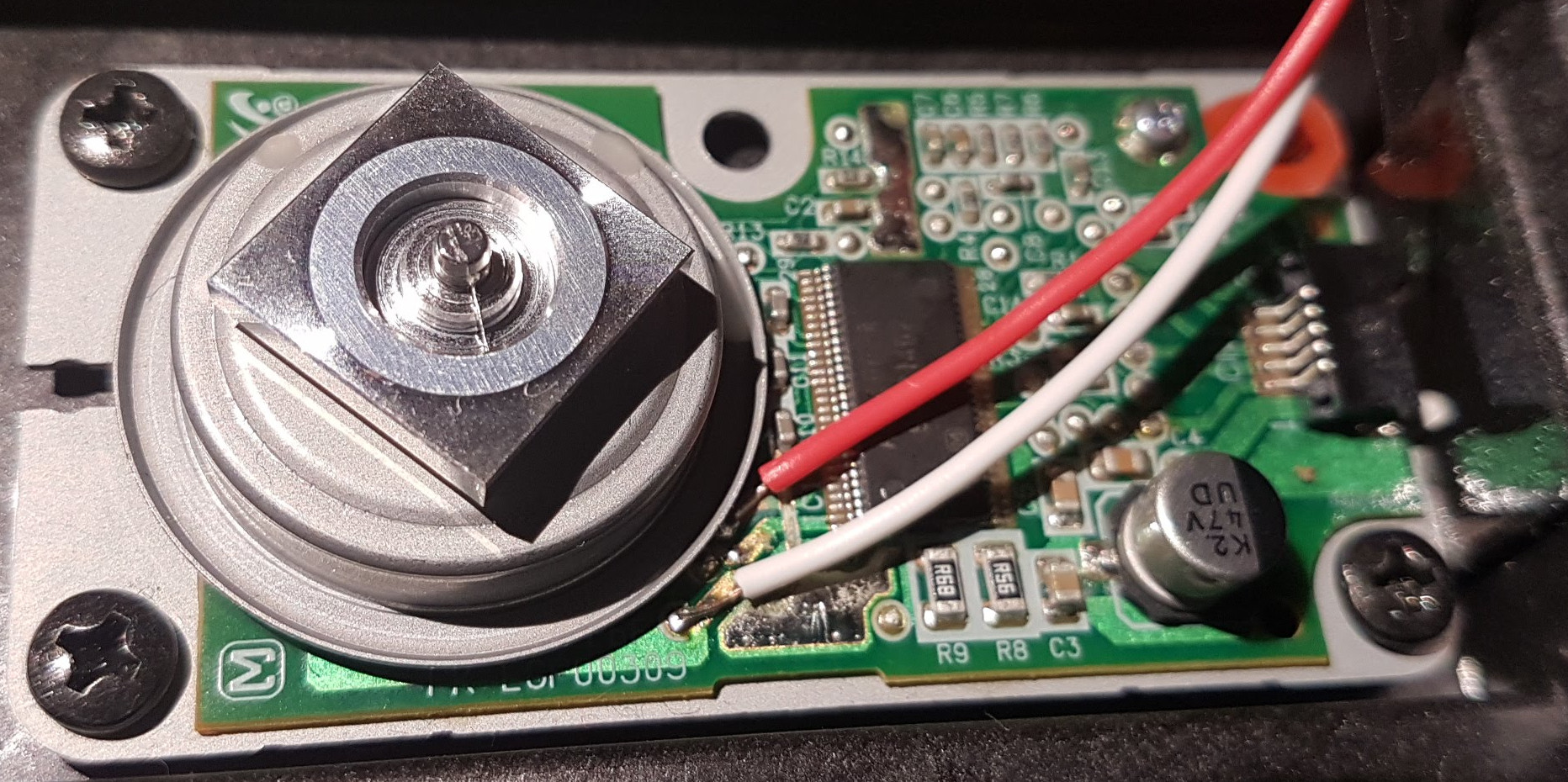
First I checked the controller chip: AN44002A. Unfortunately I could not find a datasheet. The best I got was the following picture:
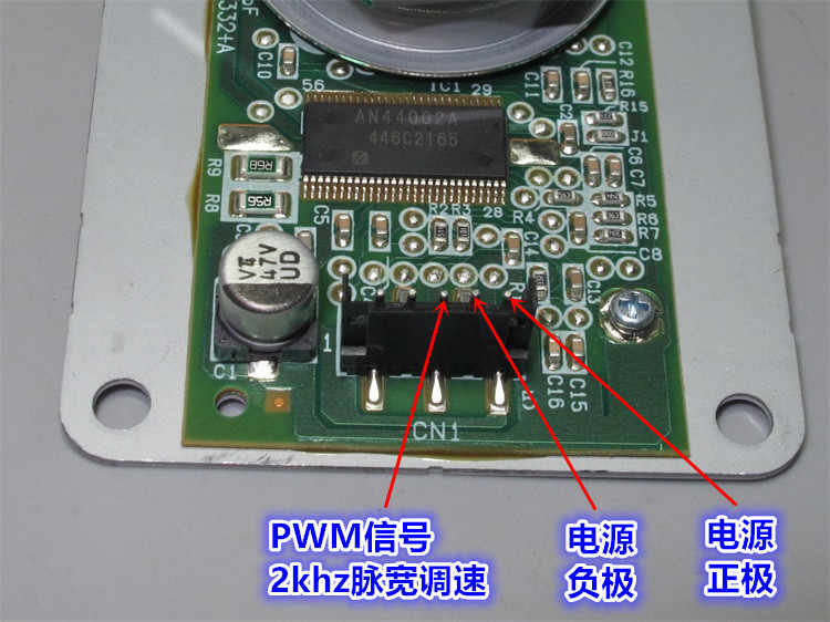
Using the google translate app on my phone I got (from left to right): “2khz pulse width speed regulation”, “power supply negative electrode” and “power supply positive electrode”. I soldered three cables to the vias close to the connector and applyed 24V. Turned out the motor driver switches on for about 2ms after each falling edge on the PWM pin. This got the mirror spinning, but it was loud and pretty fast.
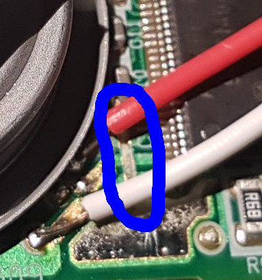
So I decided to roll my own motor driver. Poking around with my oscilloscope I found that the three connections you see the wires soldered on in the photos connect to the motor coils. I cut the connection on the PCB and connected the three wires:
Then I built the following circuit on a breadboard:

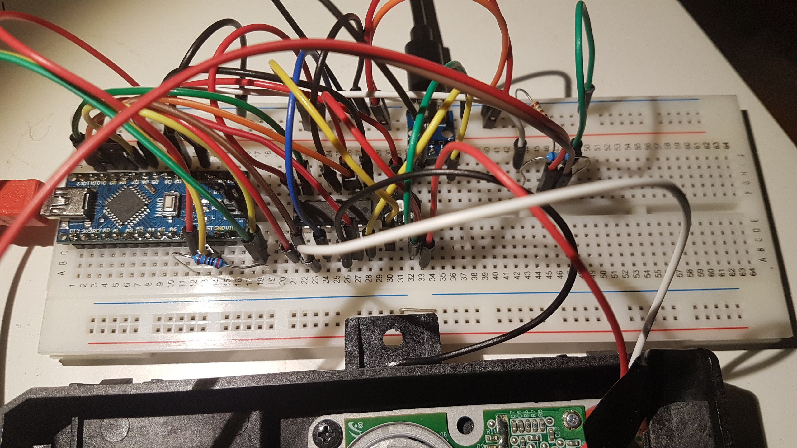
On the arduino I used timer 2 to generate a PWM signal at 62.5 kHz toggling the enable input of the L293D. And the following step list is used to drive the coils:
uint8_t steps[] = {0b110, 0b100, 0b101, 0b001, 0b011, 0b010};
The following video shows the mirror in action: